Concealed Car Lift
June 2025
OBJECTIVE:
This project was an exercise for Mechanical Engineering Design, in which I worked in a team of four to design a car lift which is installed under a garage floor and sits flush with the ground, extending to lift a car five feet in the air. We designed and performed stress analysis on a scissor lift mechanism, sized a motor, designed a planetary gearbox, and selected a lead screw to actuate the system.

PROCESS:
We began by selecting a two-stage scissor lift mechanism based on floor space constraints. Two stages were necessary to achieve the desired vertical extension without having an excessive footprint on the ground.
I used SolidWorks to design and 3D print a scale model of the initial design, shown on the right.
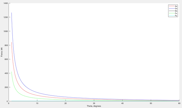
With the concept of the system decided, I wrote a MATLAB script to determine the force components acting on each linkage as a function of its angular position, assuming an average car weight (~4000lb). The resulting plot from this is shown below.


After quick stress calculations based on the bending and axial loading in each member, it became clear that the stress were much too high for the current linkages. So, I created another MATLAB script to determine the minimum allowable moment of inertia and cross-sectional area of each member based on a safety factor of two. I performed fatigue analysis based on equations from Shigley's Mechanical Engineering Design on each linkage to confirm that our components would maintain this safety factor after 10,000+ loading cycles. After using the new parameters in our CAD and accounting for stress concentrations at pin locations, we conducted FEA on each linkage. The results of the simulations agreed closely with the predicted stress from my previous analyses, and samples are shown below.


Similar stress analyses were conducted for the rest of the components in the car lift using similar methods. More complex geometries were simplified to treat them as beam deflection or compression systems for the purpose of hand calculations, and addition FEA was conducted on each component. We found that even with generous assumptions, the FEA results agreed with our predicted values of stress in most cases.
Once all of the individual components were design, we began bolt analyses for the connections of each member, treating the pins joining them as bolts under shear. Using equations and stress theories from Shigley's Mechanical Engineering Design, we selected appropriate bolts for each connection, standardizing them whenever possible.
The next challenge of the design was finding an appropriate power screw and motor. The motor needed to provide enough torque to actuate the power screw under its maximum loading, occurring at the lower position in the lifting cycle. Using the torque rise equation shown below, along with parameters from a selected power screw, I calculated the peak torque required from the motor.
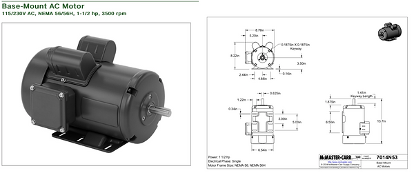
We then used the Distortion-Energy Theorem to validate the selected lead screw, and confirmed that it had a safety factor of 2.12 against thread damage. Using the required torque and RPM to raise the car fully in a given time, we determined that the required motor power was 1.5hp. I found a suitable motor on McMaster, shown below, and we began the planetary gearbox design.
I was responsible for designing one stage of the three-stage planetary gearbox, and, using gear stock available on McMaster, determined the required face width for the gears to maintain a safety factor of 2 in each gear. The three stages combined allowed 1.5hp to be transmitted at ~27rpm, yielding approximately 3500 in-lb of torque.
RESULTS:
While the final profile of the car lift was larger than we initially planned, the design is theoretically capable of lifting a midsized sedan up and down 5ft in the air 10,000+ times while maintaining a minimum safety factor of 2 against fatigue and yielding. Each component underwent detailed stress analysis, fatigue calculations, and FEA, and the powertrain was designed to withstand the same conditions using commercial-precision quality. This project was a great exercise in mechanical design, and I developed my skills in stress analysis, MATLAB, component selection, CAD, and technical writing.